Sinclair C5 Gearbox Remade
Another retro project has been occupying my thoughts for some time now. I have a pair of Sinclair C5 electric vehicles (released in 1985) sat in the garage.
One of the main problems with the C5 is that the motor gearbox components are no longer available, which means if your gearbox disintegrates due to a bit of harsh acceleration (or just old age), you face a challenge finding replacements.
The first thing I'm doing is recreating the gearbox components in CAD. The aim is to make them as close to the originals as possible. The main exception is the main gearbox cog, which I intend to have 4 posts rather than 3. This will spread the load out better, making it stronger and better prepared for the higher speeds that you get when running the motor at 24V (another mod for the future!).
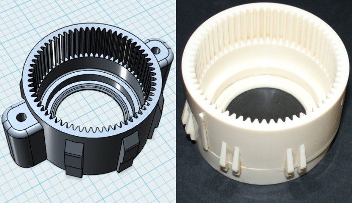
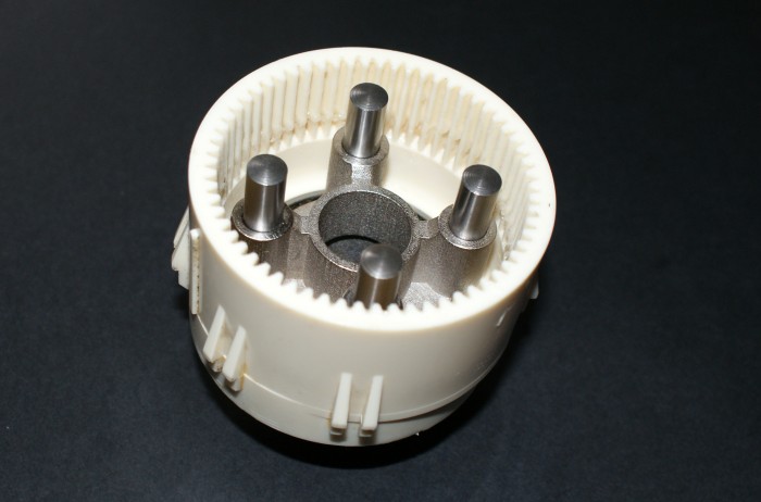
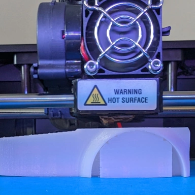
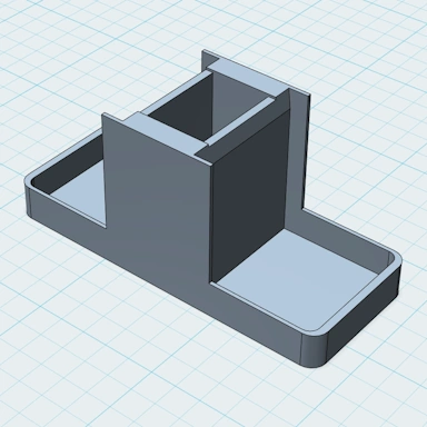
So, first up is the outer gearbox housing. This differs from the original in that it is intended to be bolted to the motor for extra strength and also for those with motors with snapped "fingers". The original outer gearbox is on the right.
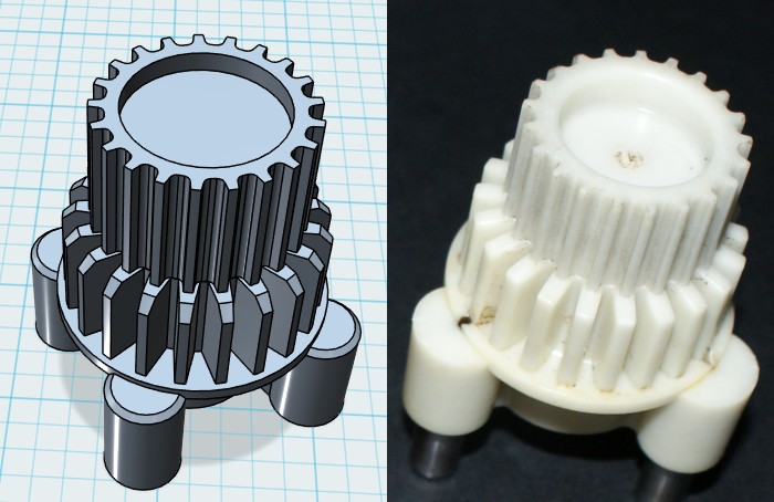
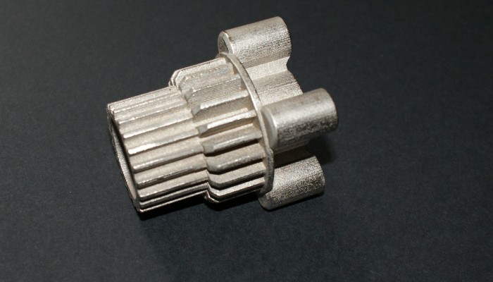
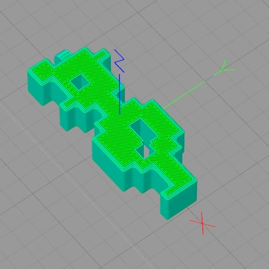
The main cog is the next item. This has to be extremely strong and will be printed in steel. The difference between this and the original gearbox main cog is that this contains 4 posts rather than 3, which the original had. As before, the original cog is on the right side.
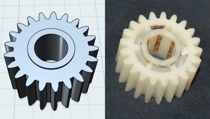
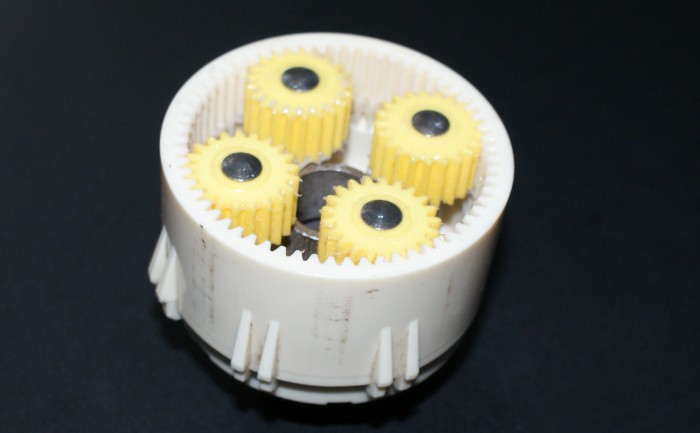
These are the small cogs that sit on the posts. They are very similar to the originals, except we have filled in the holes in this design for a bit of extra strength. We will be using four of them rather than the three that the original gearbox used.
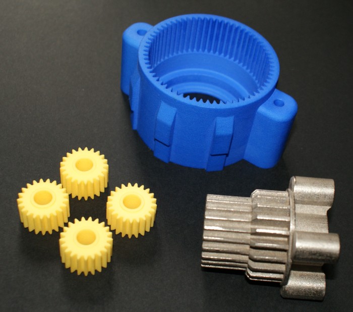
To make these strong, they will be printed in nylon and steel. As my printer is unable to print in these materials, I am using the excellent 3D Printing Services of Shapeways to turn the designs into solid reality.
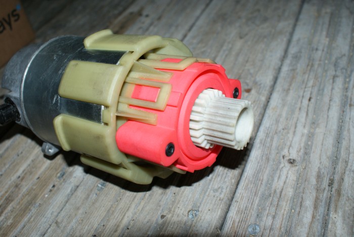
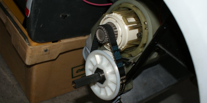
We shall be testing the components separately, so on this motor, we are testing the new outer gearbox housing in a nice red color. Everything else in this gearbox is original.
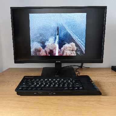
And on this motor (which is mounted in the C5), we have the metal main cog with the four yellow small cogs inside.
If you're interested in following the progress, I will be updating this article in the future. You can also follow progress and ask questions by posting comments below or following us on Twitter or Facebook.
Submit a Comment
Your comment has been submitted. We will review it before displaying it on our website.
Comments

simon deaneMay 30, 2015 12:51
Hi,I am very interested to see your progress on the gear box,I myself have been working and testing various ideas on the gearbox for some years now.Chas told me that 4 cogs dont work because 3 of them engage with the internal gear but the forth cant turn enough to take the load at the same time the other 3 are all in contact with there 20 degree pressure angle with the internal gear ,but i dont see why it woudnt,i think he is measuring something wrong,anyway through my experimenting i have found that 6 planet gears work perfectly one every 60 degrees,the planet gears interlock with each other and doing it this way is incredably strong.I dont yet know how you are making the metal cogs,but i can tell you that you can not have steel on steel the friction and heat and metal debris will be mental,you have to bore out the mod 1 gear to 12mm and fit a oilite bush 12mm o/d 8mm i/d and ream out to fit the dowell pin nicely,and also you cannot run this metal cog version on grease,the metalic debris with the grease turns to an abrasive soup like valve grinding compound and the gogs will be worn out in no time,i have tried i know,what you have to do is run it with 6ml of ep 90 gear oil,what i have done is fitted 125mm of 6mm o/d (looks like car window washer tube)but in actual fact i have used a old car battery breather tube because i found the i/d was larger.I then drilled a 5.75 mm hole at the lowest point of the gearbox and glued it in with JB weld,i then got a strong neo ring magnet 6mm i/d 10mm o/d and slid it up the tube so it is about 10mm away from the outside of the bottom of the case this then attracts all the metal debris out of harms way.The fill/drain tube is blocked off with a m5 bolt and a small o ring.a small hole about the same size as the bottom hole must be drilled in the top of the gearbox,not as a fill tube but a breather so as no pressure is built up,the posistion of the 2 holes are critical.Do not fill from the top as the oil is so thick it wil take over a day to trickle down to the drain/fill tube and air is trapped in the tube.Go to the chemist and buy a 5ml measuring syring,you can just get 6ml in there and fill from the bottom this eliminates any air in the tube and the need to wait for the oil to eventually fill the tube and exspell any air.If you try my idea you will notice that after filling with 6 ml of oil for the first time that only about 3/4 ml will drain out because 2 or 3ml is left coating the internal gear and cogs,but the second time you do an oil change 6 ml should drain out(only drain the oil when it has been in use and is hot.)Use a 2 RS rubber shielded gearbox bearing(these are not the best for friction and heat but will stop any oil seeping out.In the case of chas,s gearbox insert it is made of ally which is the fastes metal known to transmitt heat,so with the friction on the dowel pins this heat is conducted to the HTD-5 drive cog and it can really get hot,very hot,so i have made a external heat sink out of 2mm ally that looks about the size of a cd (11cm) with many holes drilled in it like a disk brake and is fitted to the end of the insert with heat sink compound and a m5 bolt,this really helps the heat situation,i have all the data about heat but it is far to involved for now.Moving on to your gearbox internal gear case,i think it is a good idea but allthough nylon is low friction i would be very amazed if it could handle the heat and tourqe,can you not 3d print in delrin ?this is what material was originaly used.My mod1 planet gears have 3 2mm holes drilled through them at 120 degrees spacing to allow oil to be forced through to the dowell pins as the teeth mesh together,the motor cog is metal and is bored out to 9.98mm and is a press fit and has no oilways,all my steel gears are made from EN24 grade steel.Hope you find this helpfull.You can email me if you want to know more at
[email protected] If you want someone to test this prototype i would be glad to help,Yours sincerly Simon Deane.
AnneJul 21, 2016 09:43
Hi Dan,
I´ve got an problem and hope you can help me. I got a Sinclair C5, but now inside the gearbox the small cogs for the transmission are broken and I´m not able to get ANY spare parts here in Germany... Can you send me these gear parts?? Or do you know where I can get them? Is it possible to get the dimensions to make them from metal otherwise? I hope very strongly you can help me...
Thank you very much!!
Anne
Tyrone HawkinsJul 24, 2018 11:23
Is there any further progress on this project, there is mention of testing the product, but nothing on the results. I have, like everyone else an ageing gearbox / motor with little hope of buying spares, so these results would be very interesting for the winter overhaul / rebuild.
Peter PescodJan 26, 2022 14:43
I have owned a sinclair C5 for many years. The main three prong nylon gearbox sprocket has become so worn that it will no longer drive the belt. These parts are now impossible to obtain but I have seen Dan Birch's articles in 2015 about reconstructing a gearbox and I wonder if you have the necessary designs and are able and willing to print them and at what cost.