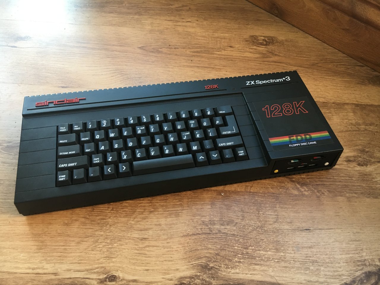
ZX Spectrum Next in a Spectrum +3 Case
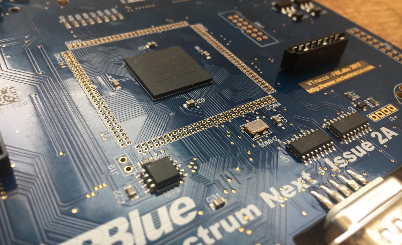
I received my ZX Spectrum Next board (yay!) that I backed on Kickstarter I'm now going to attempt to mount it inside my Spectrum +3 case.
I had intended to create a dedicated 3D printed laptop case for this board; however, there are issues currently with the firmware that prevent the board from working on certain HDMI/VGA displays, so I will be hanging fire on that one until the issues are sorted out. In the mean time, I need to house the Next board somewhere, so why not inside an old Speccy +3?
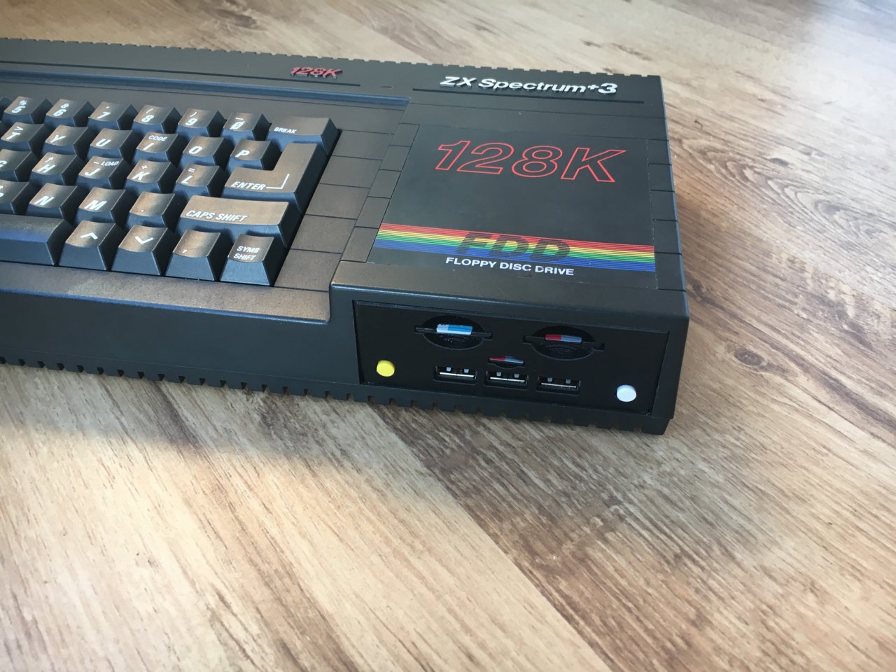
New Multi Purpose Drive Bay
As the Next board supports things like the WiFi module, Raspberry Pi Zero, real-time clock, 2nd SD card, etc., I set out to make full use of these. This includes adding in a USB hub for the PI which will be routed over to the (now empty) bay that used to contain the +3 Floppy Disk Drive. Currently, the board firmware only supports PI USB keyboard and mouse devices, but further down the road, it is inevitable that there will be a lot more support for a wide array of devices!
As well as USB ports, the old Floppy Disk Drive bay will also host both Next SD cards and the PI Micro SD card (to make software and OS updates easier than having to open the machine up). On top of these, I will also have the two buttons M1 and Drive mounted on the front of the old drive bay for easy access.
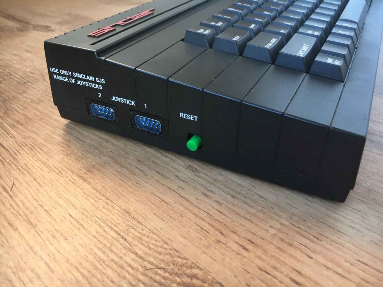
Joysticks
The Spectrum +3 has two joystick ports on the left-hand side of the machine. On the Next board, the joystick ports are mounted on the front. So, for this, I will create a pair of small extension cables to route these sockets from the front to the side, where they belong on this machine! A small 3D-printed adapter will be used to fill the oversized joystick holes in the +3 case.
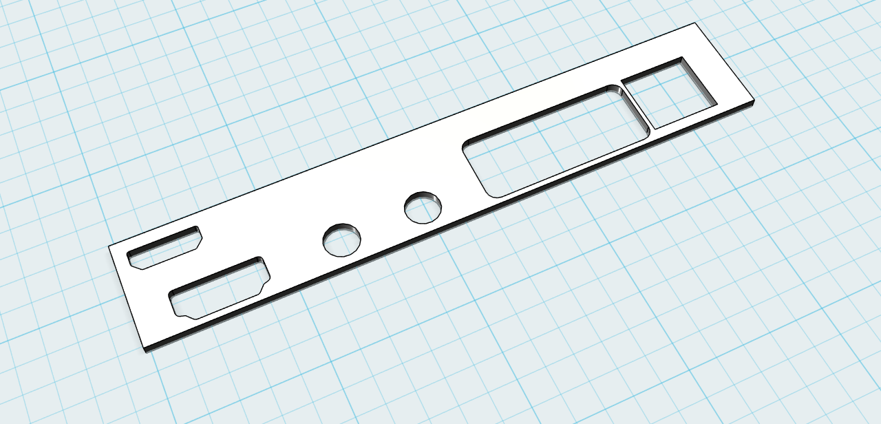
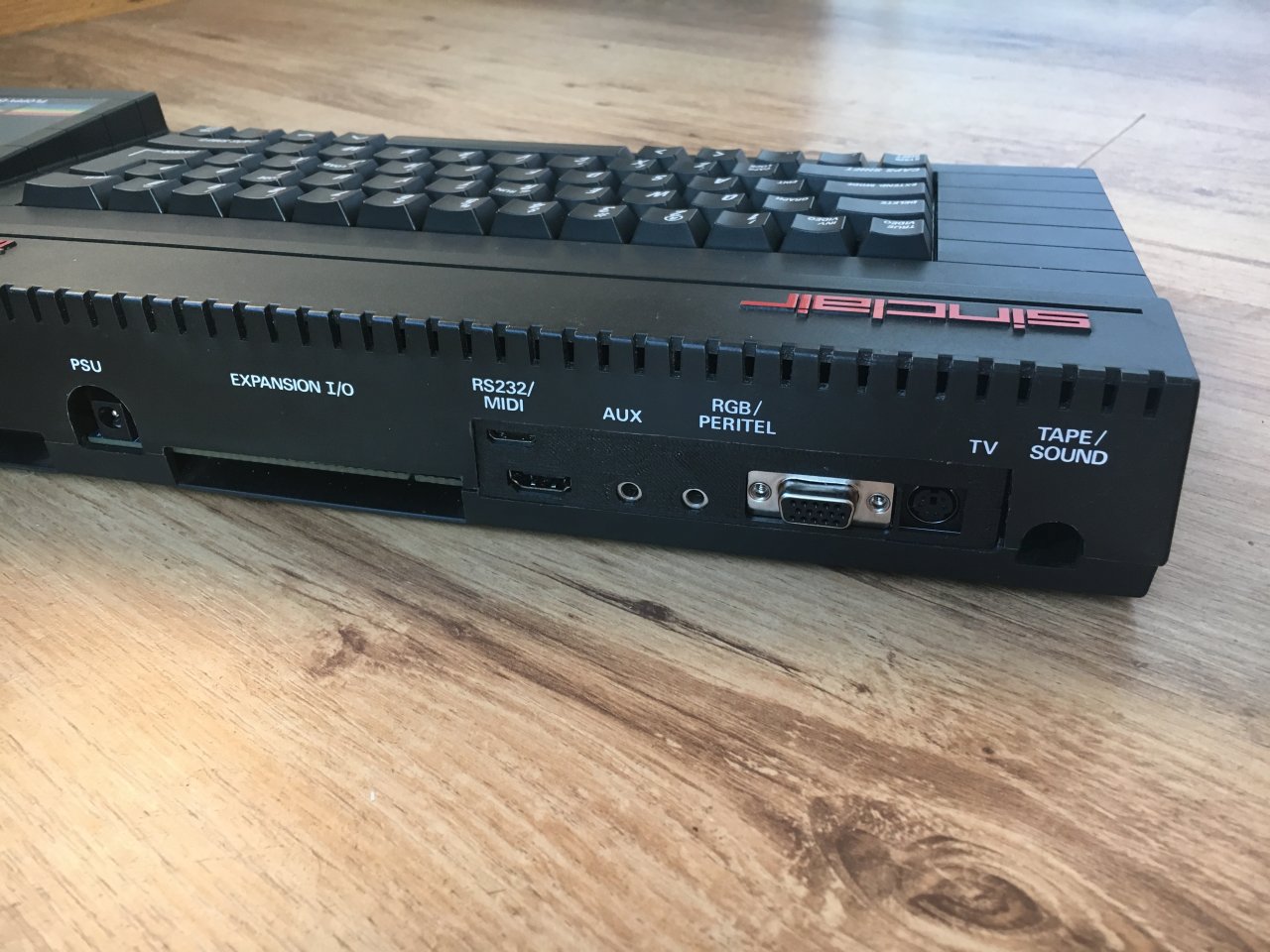
Back Panel
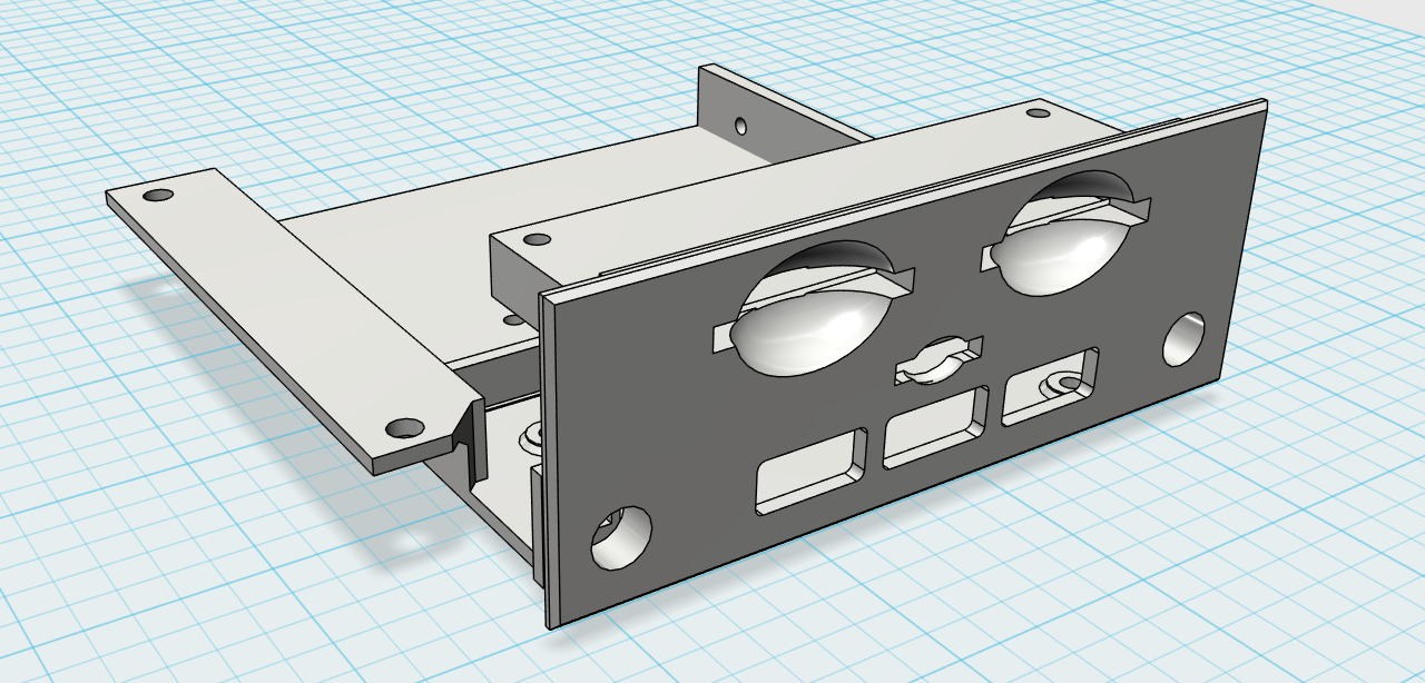
One of the main issues with fitting the Next board into a +3 case is the different connections that are needed on the back. The Next has 2 HDMI sockets (the PI Zero has a mini HDMI socket), VGA, ear/mic, and PS/2 sockets on the back, which do not line up with anything currently on there. To keep it as neat as possible, I decided to drill out a large rectangular section on the left side at the back and create a 3D-printed back panel to cover the gaps in the Next connector sockets to keep it looking as tidy as possible.
Assembly Time
Components
- Spectrum +2 (Grey) Keyboard Membrane
- Raspberry Pi Zero USB Hub (Ebay)
- Power Switch (Ebay)
- Colour Push Buttons x3 (Ebay)
- 10-way Ribbon/JTAG Cable (Ebay)
- Male/Female Joystick Sockets (Ebay)
- 8 Core Cable for the Joystick Extension Cables
- Micro SD Extension (Ebay)
- SD Extension x2 (Ebay)
- Right Angled Header Pins (Ebay)
- 2 Pin Connector (Ebay)
- 8-way Ribbon Cable (Ebay)
- M3 Screws 6mm
- 8-way Keyboard Connector (sellmyretro.com)
- Plenty of wire/heat shrink tubing!
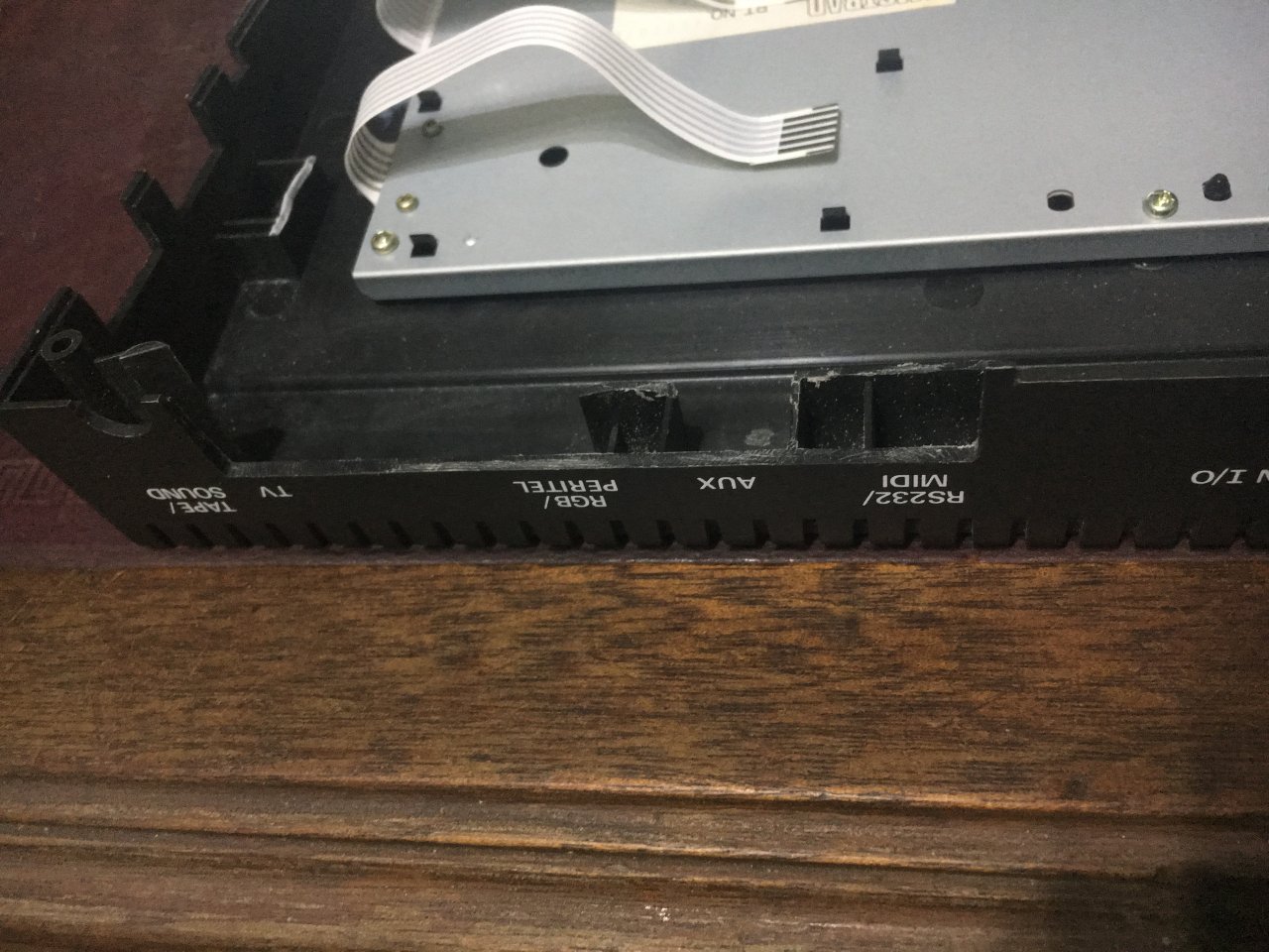
Cutting the Case
The back of the case needs to be cut out with a Dremel and then filed down to create a 113mm x 20mm space. This will cover the area currently occupied by the RS232, Aux, RGB, and TV connectors:
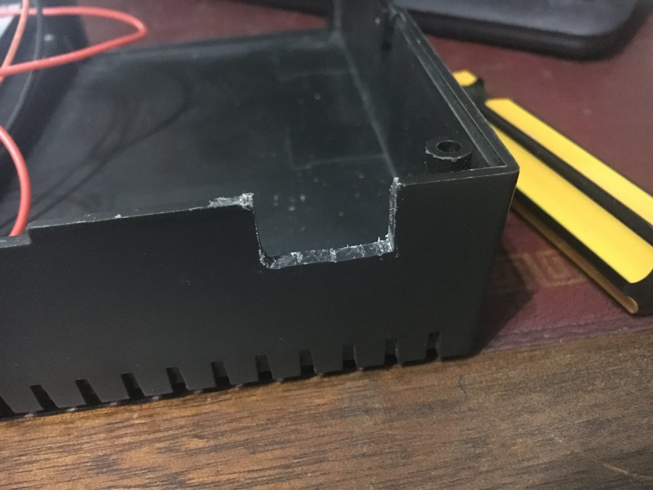
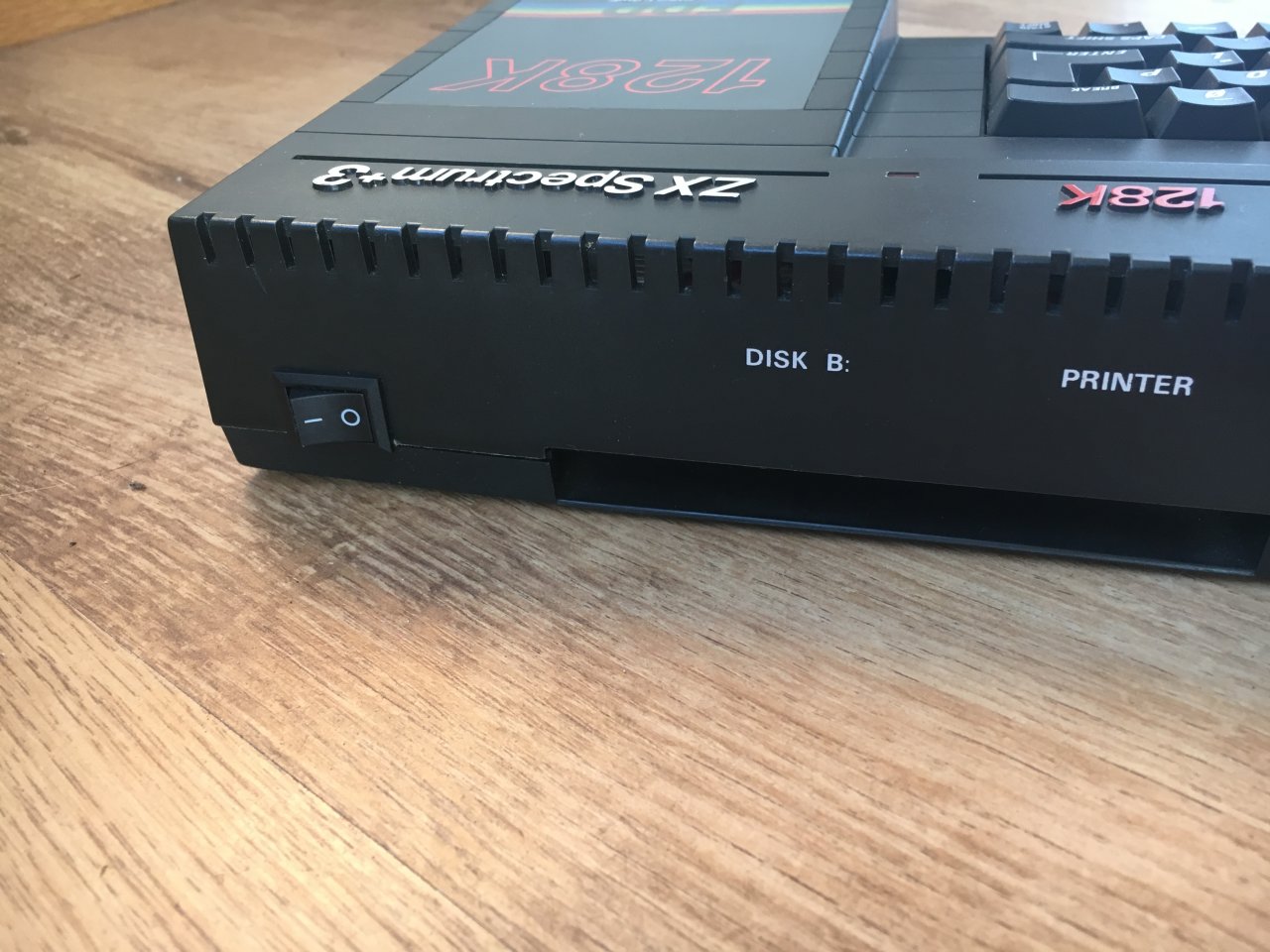
Cut out a small rectangle the size of the power switch on the right-hand side:
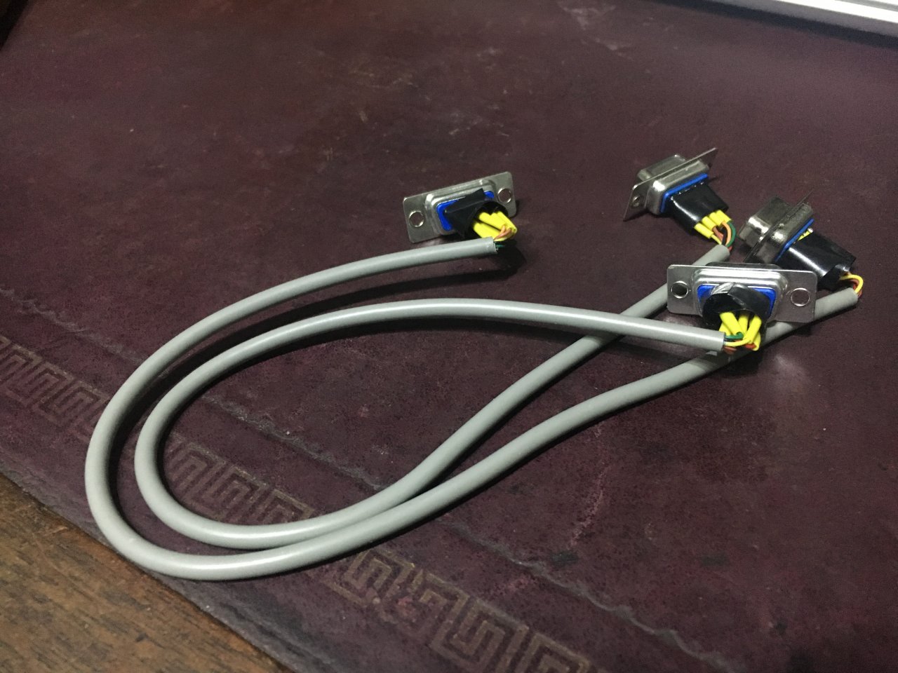
Joystick Extension Cables
I couldn't find any suitable extension cables off the shelf, so I made some myself using some 8-core cable I had lying around and some male and female DB9 connectors. The cable needs to be long enough to go from the +3 joystick ports to the Next ports on the front of the board:
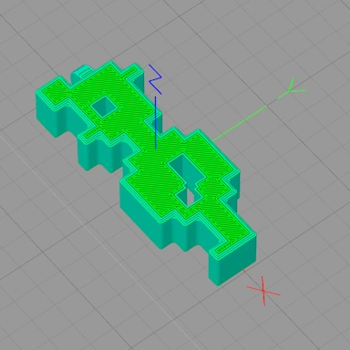
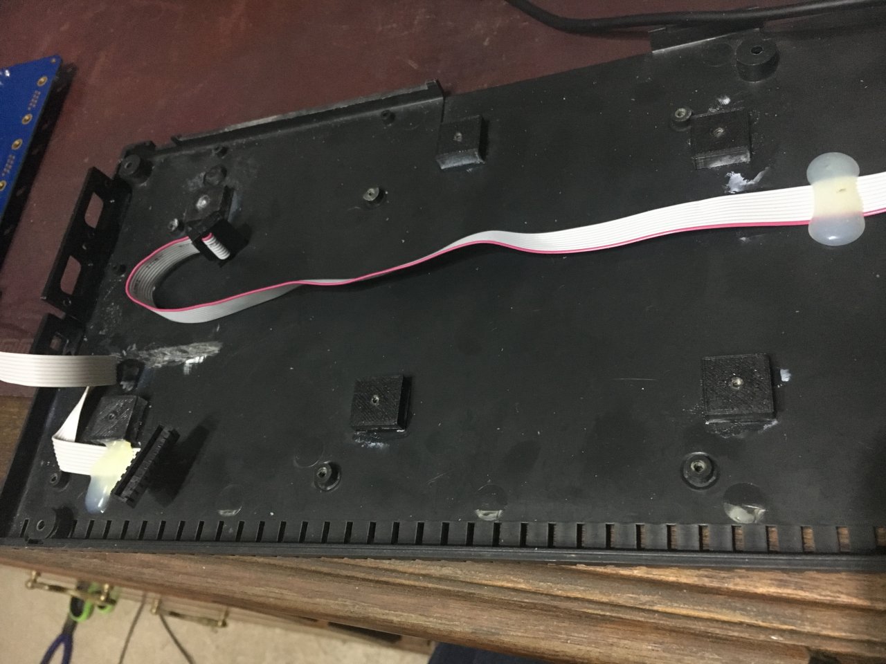
PCB Plastic Spacers
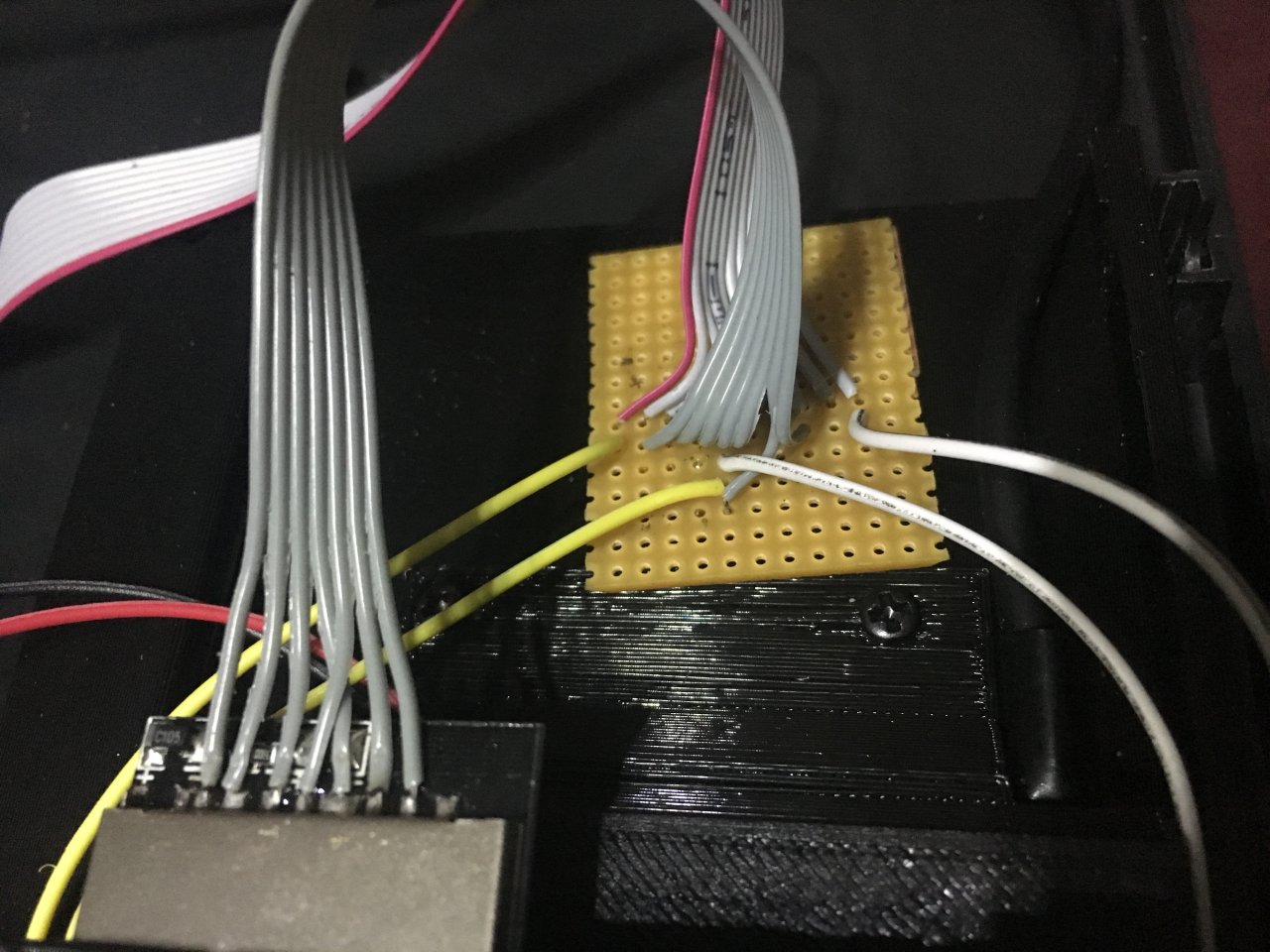
I 3D printed some plastic spacers (6mm tall); the 3D model file is included in the download below called "screw-block", I made 6 of them and glued them to the case where the screw holes lined up on the PCB. Once the glue was set, the PCB could be mounted. Also shown here is the ribbon cable running from the Next daughter-board connector over to the +3 disk drive bay. This cable contains the SD card signals and M1 & Drive button connections. I soldered each connection to a small piece of PCB strip board, which will be used later on:
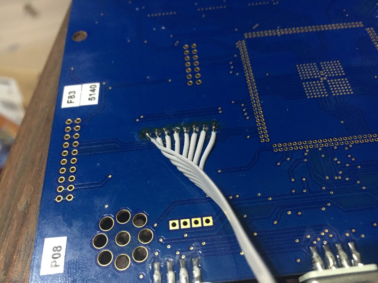
Extending the Keyboard Connector
The 5-way keyboard connector on the Next board is already in a suitable position for the Amstrad keyboard membrane; however, the 8-way connector (on the right side) needs extending and bringing over to the left side in order for the keyboard to be connected up. I simply soldered some ribbon cable under the PCB, took it all the way over to the left, and glued it down (see the image above). Simply solder the ribbon cable to the existing connector pins:
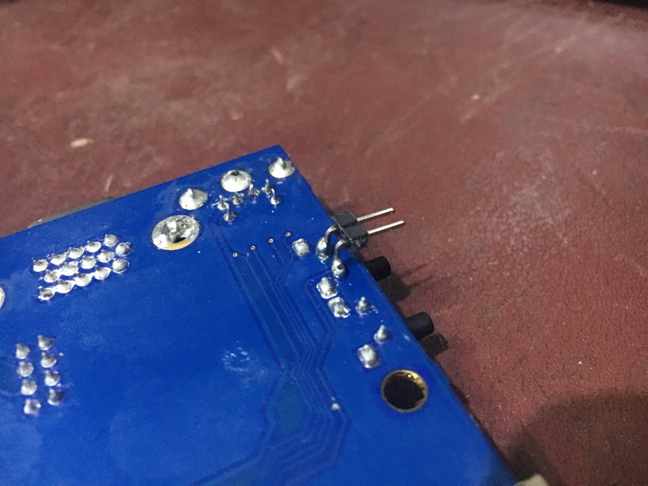
Reset Button
The reset button needs a little modification to get working. I soldered a pair of right-angled header pins to the reset button pins on the underside of the PCB. From here, I glued a 3D-printed adapter into the existing reset button hole in the +3 case. Once the glue was set, I added the yellow push button and connected it to the angled header pins:
USB Hub
If you are using a USB hub, this should be added to the 3D-printed drive bay first and connected up to the PI Zero. There is no room to connect a USB cable via the sockets. For this, I cut some spare USB cable to size and soldered the connections to the PI Zero and the USB hub.
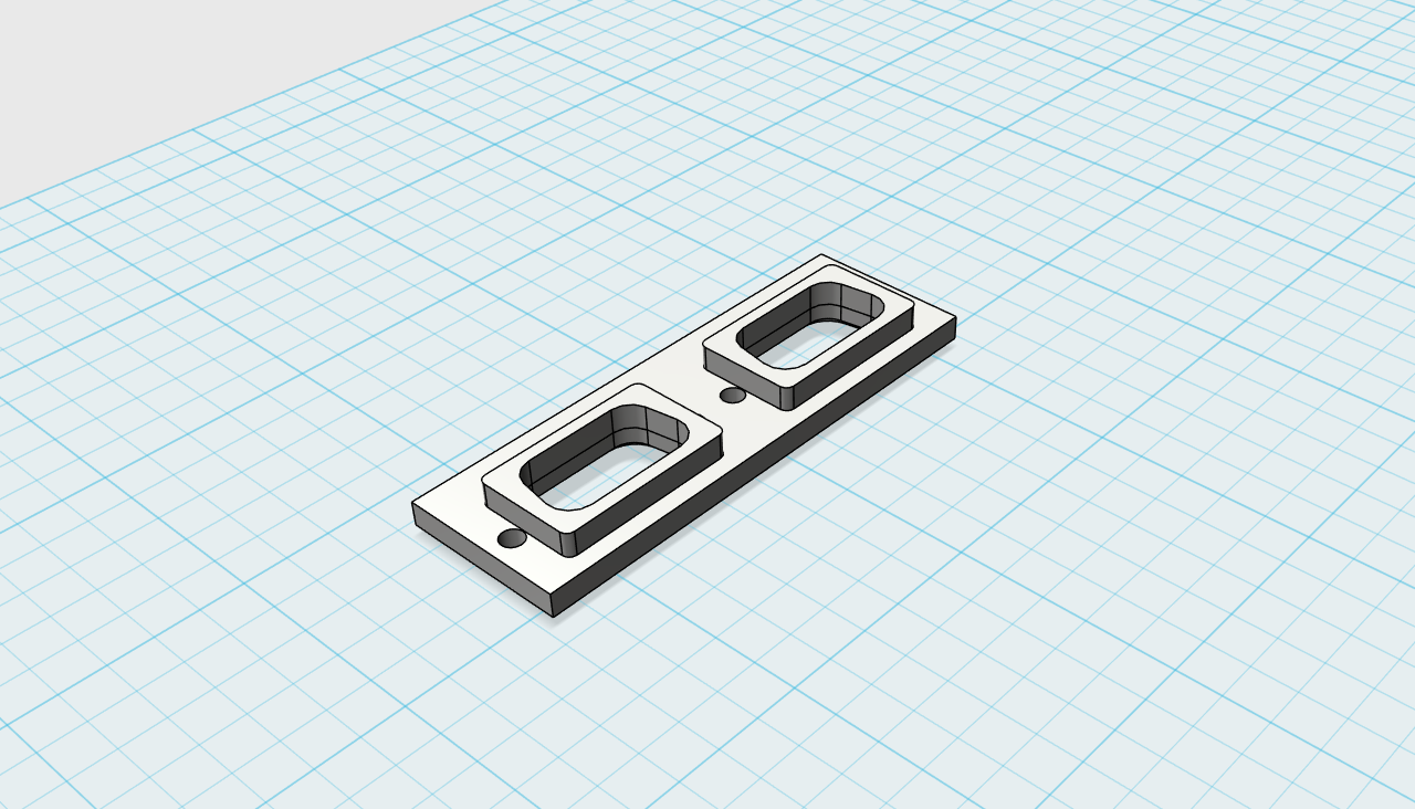
M1 and Drive Buttons
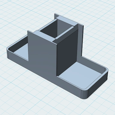
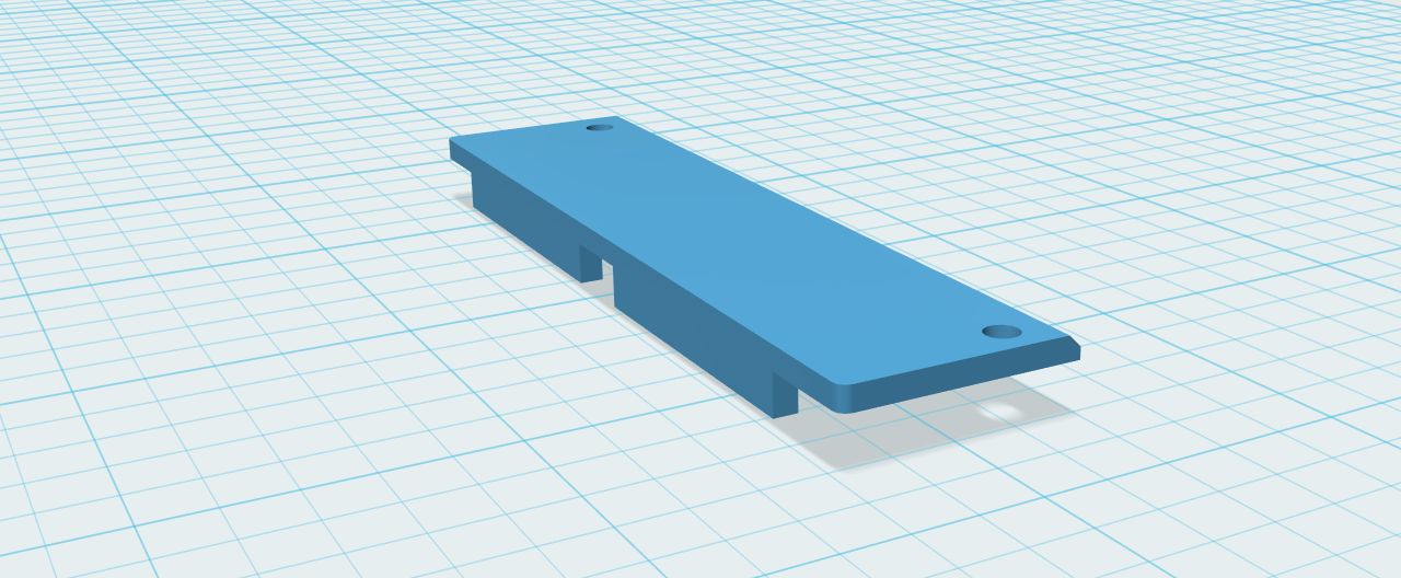
These two buttons can be added to the 3D-printed drive bay; they should slot perfectly into the holes in the bay. Once added, a separate 3D-printed cover (drive-plate-top.stl) is placed over the USB hub and behind the buttons. There are two screw holes in this that will align with the main drive bay and secure it in place.
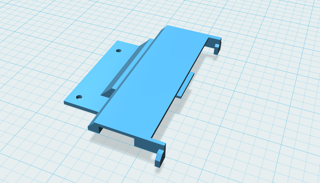
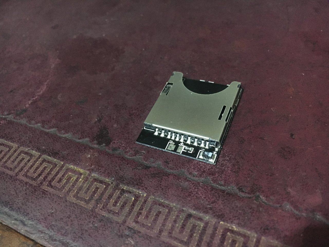
SD Card Sockets
I bought 2 SD card extension cables and removed the cable and SD card, leaving only the socket on the PCB:
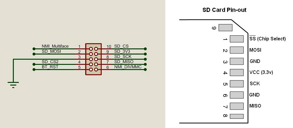
With both SD card sockets ready, I soldered on some ribbon cable from the SD card connector to the PCB strip board I made earlier, ensuring I matched up the signals correctly. I only did this for one of the SD card connectors due to the Next firmware only supporting one SD card at this time.
The pinouts for the Next daughter board connector are available on the Spectrum Next Forum. I've included the pinouts here for reference:
With the SD card sockets inserted into the 3D-printed drive bay, there is another, separate 3D-printed cover (drive-plate-top-2.stl) that is placed on top of the drive bay. Again, there are two screw holes in this that will align with the main drive bay.
PI Zero SD Card
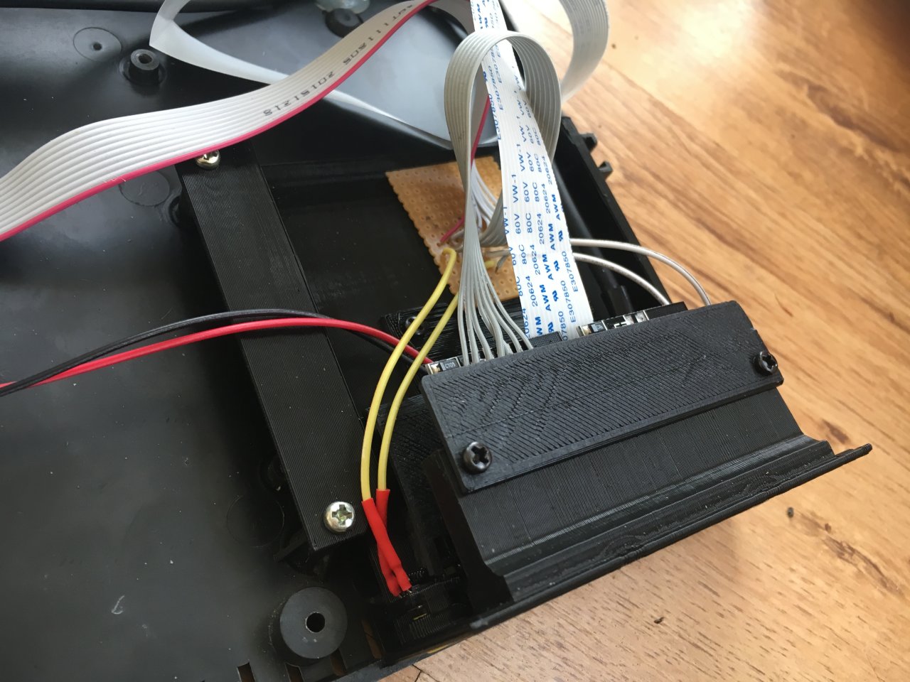
The PI Zero SD extension cable can now be fitted to the drive bay. This is simply pushed into the space in the 3D-printed drive bay and glued in place.
A Look at Everything that was Done
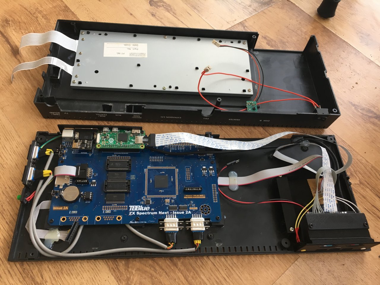
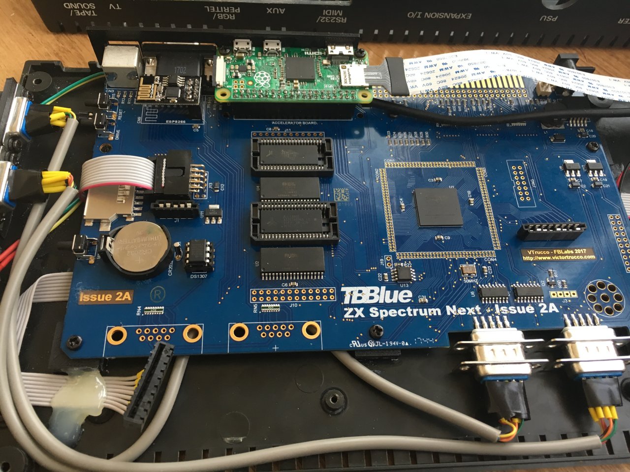
After fitting it all together, which involved a lot of glue, here is what the machine looks like inside:
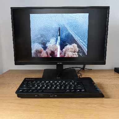
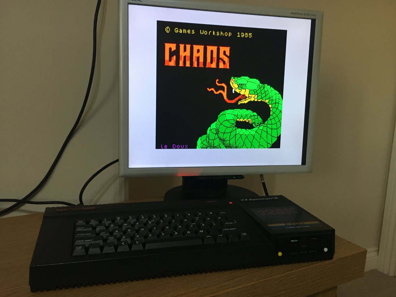
All Complete
With the machine put back together, it is guaranteed to get much more use now that it has Spectrum Next inside it!
File Download
Click the link below to download the file(s):
Spectrum +3 Next Conversion: spectrum-plus-3-next-conversion.zip (813.38kb)
We provide all files as-is, without any kind of warranty, for use in your own personal projects. They may not be redistributed or sold without permission.
Submit a Comment
Comments
DRJan 17, 2018 14:36
Superb!, gonna have to dig out an old Plus 3 caseJan 22, 2018 17:33
QuarXFeb 21, 2018 22:51
Love read your article, and many thanks for share the fantastic STL files.
BaggersOct 30, 2018 16:42
I really like the +3 and love how you put all of the SD readers in the drive bay, including the Pi's one.
SavvasApr 28, 2021 20:41
Gavin HorricksFeb 14, 2025 12:47